Use cases
A Step-by-Step Guide to Building a Sheep Tracking Device
A straightforward way to prototype an agricultural technology products from generally available components.

May 14, 2020

Making Agtech Accessible
Many IoT developers have strengths in hardware, networking, or software. What we believe makes IoT applications especially difficult to bring to market is the cross-functional team effort required. Building expertise in all three aspects of technology isn't an easy task for any company, let alone a developer starting with their first prototype.
Luckily IoT companies are modularizing technology so it's quicker than ever to prototype an IoT product to enable you to quickly and iteratively test a solution with your potential customer base.
This is a guest post written by Danie Conradie. It demonstrates a straightforward way to prototype an agricultural technology (Agtech) product from generally available components.
Scenario
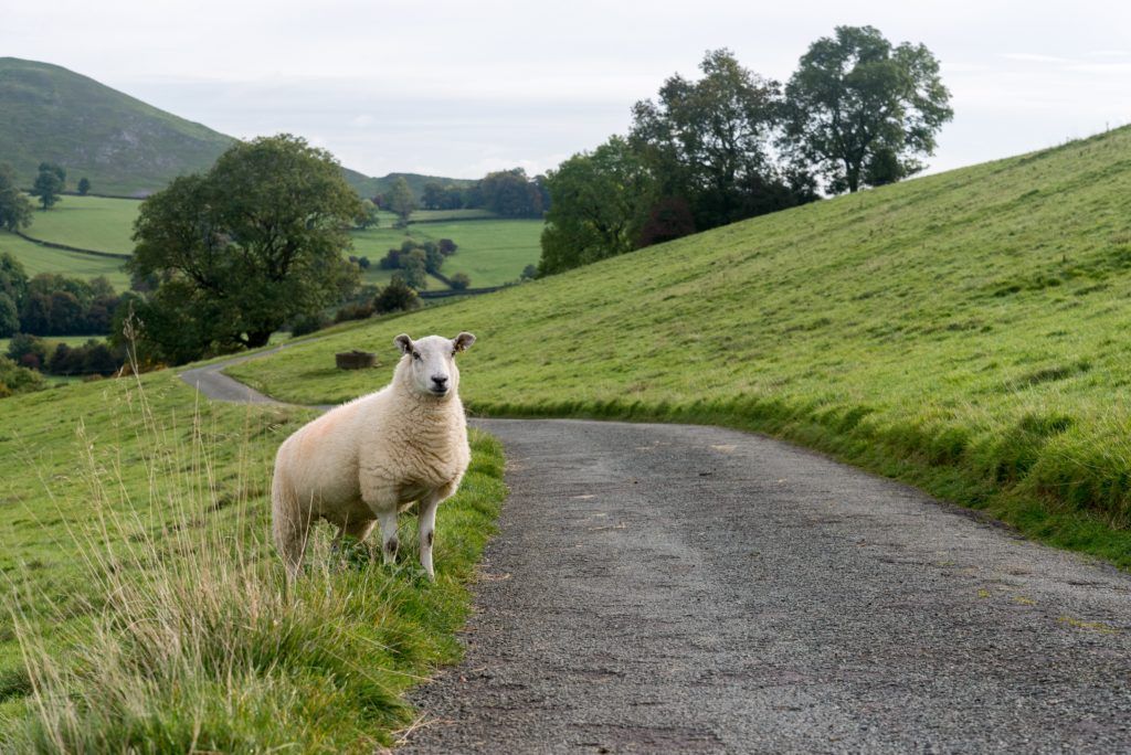
The ingredients of every single meal you’ve ever had was produced by a farmer. Agriculture literally feeds the world, and the opportunities for technology to help increase output and improve efficiency is almost endless. In this tutorial we’re going to go over building a prototype for a livestock tracker, all the way from hardware to backend software, and also cover some pitfalls of proof-of-concept prototypes.
Farmers face a multitude of challenges every day, and in South Africa, where I live, one of these challenges is livestock theft. Reported losses totaled over $83 million in 2018/2019, and has been steadily increasing by 3% year-on-year. This means that there is a real need for IoT solutions to help farmers secure and monitor their livestock, which also means that sustainable businesses can be built to serve those needs.
Solution
To help combat livestock theft, I'll be building a tracking device that can be worn by livestock and report location and behavior to the farmer via a computer or mobile device. The goal is not to build a market ready product, but to put together a functional prototype that can be used as a test platform to get customer feedback, and identify the unexpected problems that often get overlooked while you’re sitting at the drawing board.
Before you start building anything, you need to make sure that you really understand the problem you are trying to solve. This usually means talking to actual prospective clients. Technical minded people like myself tend to skip this step because prototyping is the part that we really look forward to. However, I’ve learned the hard way that doing so can easily lead to throwing a lot of time and money down the drain, because what you thought the client needed, and what the client actually needed was not the same thing. When a client needs to travel from point A to point B, don’t assume they need an intergalactic space rocket. Spend a little more time talking, and you might find that they only really need a bicycle to visit a friend a few blocks away.
In my scenario, cattle and sheep are usually stolen by cutting fences, and herding them to a waiting truck at night. From talking with farmers I also know that a low maintenance solution is incredibly important. They don’t want to catch cattle every few days to change batteries, or constantly keep an eye on the backend of the system. These are all things I need to consider when creating the solution.
Components
Since this first prototype is primarily a learning experience, I want to use off-the-shelf components and existing online services that will allow me to get up and running quickly. The basic solution will look like this
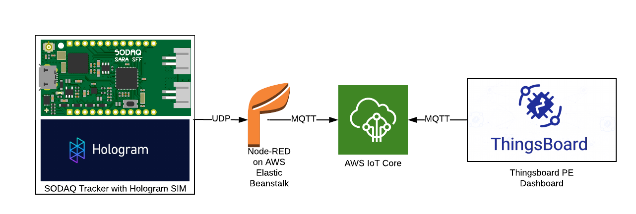
A Sodaq cellular development board with a Hologram SIM will send small UDP packets to a Node-RED instance running on AWS Elastic Beanstalk. Node-RED parses the data and sends it via a secure MQTT connection to AWS IoT Core. A ThingsBoard instance is connected via MQTT to AWS IoT, which processes and displays data for the user. The motivation behind each of these choices is covered below
Electronics
The Sodaq SARA SFF R412M Cellular/GPS development board was covered in a recent post about cellular development boards on the Hologram blog, it is an almost perfect fit for my purpose. It uses the popular ATSAMD21G18 microcontroller, which is also used in the Arduino Zero. Connectivity is provided by a uBlox SARA R412 multi-standard cellular modem, and it includes a uBlox 8M GPS, and a LSM303AGR accelerometer/magnetometer already on board.
The excellent documentation on the Sodaq website contains a number of tutorials and code examples, which means a much quicker easier process to get it working. There is even open firmware to turn the board into a functional Universal Tracker, which provides a very good starting point for our application.
Connectivity: Hologram SIM
Since this tutorial is sponsored by Hologram, this would seem obvious, but the Hologram platform gives some real advantages. With almost global coverage on the SIM card I don’t have to worry about testing in different locations, and I can keep an eye on data usage for every single connection, and manage data allocations.
Routing: Node-RED on AWS Elastic Beanstalk and AWS IoT Core
AWS IoT Core is an excellent platform for routing IoT data from devices to cloud services and other devices. It’s very widely used and can be scaled to any number of devices, from a few prototypes to millions of production devices. Most IoT cloud platforms have a can integrate with AWS IoT Core, so we can easily test out different platforms without having to reconfigure devices every time.
Unfortunately setting up the authentication required to connect to AWS IoT Core directly from the resource constrained Sodaq board is not a trivial exercise. I want to get up and testing as soon as possible, and the firmware that I’m using as a starting point already has UDP messaging implemented. UDP has the advantage of being extremely light weight, with packet size in my implementation being less than 100 bytes.
To connect my Sodaq device to AWS IoT core, I’ll be setting up a simple UDP to MQTT link using Node-RED. It will run on the AWS Elastic Beanstalk app hosting service. Node-RED is an incredibly powerful and flexible tool for IoT, especially during prototyping. It’s basically a flow based GUI wrapper for Node-RED, with a lot of pre built functionality available so you only have to do the bare minimum of coding.
User Interface: ThingsBoard Professional Edition Cloud
ThingsBoard is a powerful backend platform with no shortage of features. The documentation is excellent and I don’t need to worry about setting up my own server. The Professional Edition includes “Platform Integrations”, which allows it to easily connect to AWS IoT and automatically add devices to the ThingsBoard as they start sending data.

Instructions
I’ll now go through the process of building the solution piece by piece.
How to Set Up AWS IoT Core
AWS IoT is the central point that ties everything together for this project, so we’ll set it up first
To get started, sign up for a free AWS Account or log on to your existing account. Once you have received email notification that your account is ready, log in to the console, search for “IoT Core”.
The first step is to set up a virtual “Thing”, and it’s associated authentication and security provision.
On the sidebar, go to Manage > Things
Click Register a Thing > Create a Single Thing. Choose a name for your thing. I’ve selected “tracker-router”. Leave the rest of the fields open and click Next.
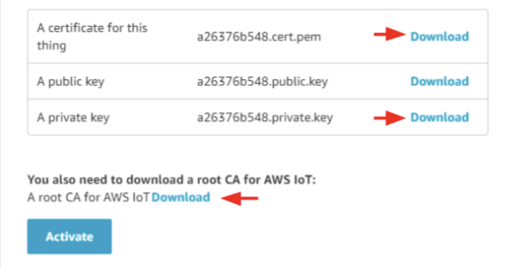
Click Create Certificate to create the authentication certificates. We’ll need the certificate, private key and the Amazon Root CA 1 certificate, so download them then click Activate
With the certificates activated and downloaded, we need to create an access policy for the clients. In the sidebar menu, go to Secure > Policies > Create Policy.
Give the policy a name, like tracker-policy. Click on advanced mode and copy the following into the policy window:
{
"Version": "2012-10-17",
"Statement": [
{
"Effect": "Allow",
"Action": "iot:Connect",
"Resource": "arn:aws:iot:REGION:AWS_ID:client/*"
},
{
"Effect": "Allow",
"Action": "iot:Publish",
"Resource": "arn:aws:iot:REGION:AWS_ID:topic/tracker"
},
{
"Effect": "Allow",
"Action": "iot:Subscribe",
"Resource": "arn:aws:iot:REGION:AWS_ID:topicfilter/tracker"
},
{
"Effect": "Allow",
"Action": "iot:Receive",
"Resource": "arn:aws:iot:REGION:AWS_ID:topic/tracker"
}
]
}
Replace REGION with the region (upper right) and AWS-ID with your account ID (On your profile page). Once done, click Create.
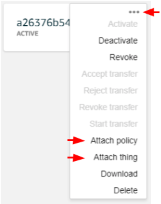
In the sidebar menu, go to Secure > Certificates, then click ··· for the certificate you just created. Click Attach policy to link the policy you just created then click Attach Thing in the same menu to link the device you created.
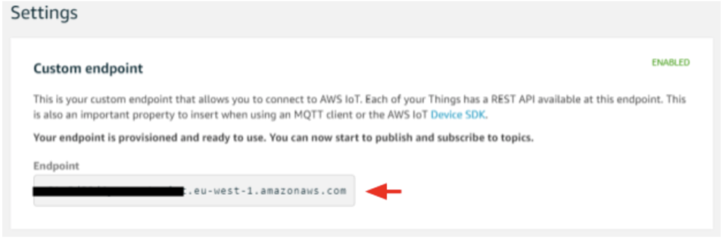
Now you are ready to connect the Node-RED app to AWS IoT core. In the sidebar, go to Settings, and take note of your endpoint URL. We’ll be using it with the downloaded certificates.
Node-RED Router
In the AWS console go to the “Elastic Beanstalk” service.
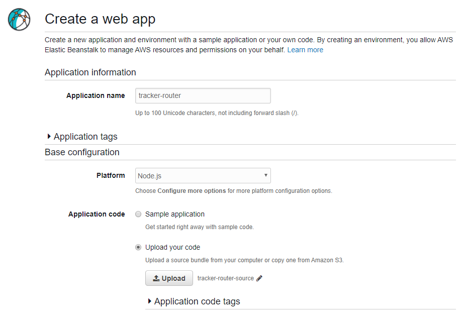
Click “Get Started” to create a new web app, then choose a name for your router app. I’m using “tracker-router”
Select Node.js as the platform, and the “Upload your code” option
Now we need to set up our app code. Clone or download the repository from GitHub.
Open the repository folder, and open settings.js in your text editor. This is the default node-red file, with the addition of the AWS settings module.export (line 21).
//AWS Elastic Beanstalk Settings
awsRegion: 'eu-west-1',
awsS3Appname: 'tracker-router',
storageModule: require('node-red-contrib-storage-s3'),
Replace “eu-west-1” with the region for your AWS account, which is visible in the upper right of the AWS console.
Once you’ve set your region, add settings.js and package.json to the root of a .zip archive. Go back to the Elastic Beanstalk console, click Upload, and select the zip archive you just created
Click on Create App. It will take a few minutes to set up the app.
Once your app has been created, it will give a “Health Degraded Warning”. This is normal, the instance first needs permission to access the S3 bucket for storing the app data and flows.
To fix this, click on Services at the top left, and search for “IAM”. On the IAM dashboard, go to Roles > aws-elasticbeanstalk-ec2-role > Attach policies. Select the checkbox on AmazonS3FullAccess, and click Attach policy.
Now go back to the Elastic Beanstalk console.
Go to Actions > View Application versions
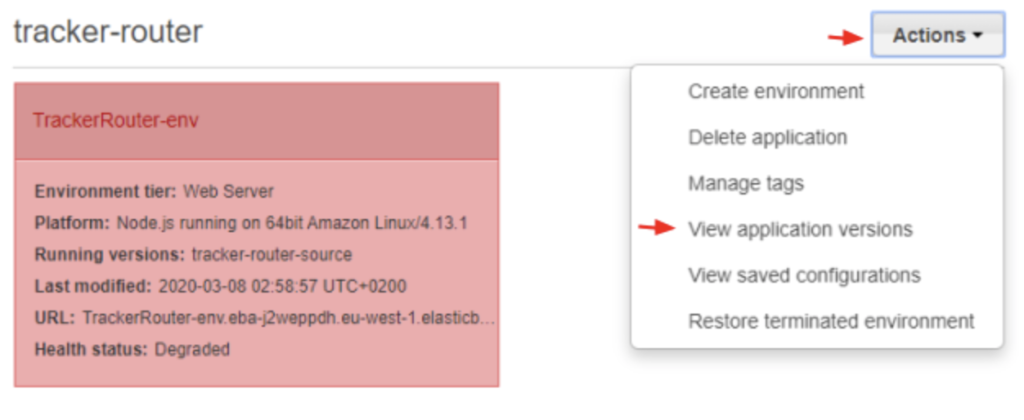
Tick the version we previously uploaded and click Action > Deploy, then click Deploy on the pop-up window. It will take a minute for redeployment to complete, after the app’s status should read “OK”.
Next you need to set up the networking ports to make sure the router can receive the UDP connections and add a bit of security to the Node-RED admin console. Click on Services and go to the EC2 console, then click to Security Groups under Network & Security in the sidebar menu.
Click on the SecurityGroup for ElasticBeanstalk environment. At the bottom of the screen go to the Inbound rules tab, and click Edit inbound rules.
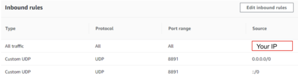
First delete the default rule, then click add rule. Make the Type “All Traffic” and the Source “My IP”. This will limit access to the Node-RED admin console to your IP address alone. You may need to update your IP address from time to time if you’re using a dynamic IP, which will lock you out of the Node-RED admin console when it changes.
Add another rule for the incoming UDP packets from the tracking devices, with Type “Custom UDP”, Port 8891 and Source “Anywhere”. Click Save Rules. The final configuration will look like this:
Still on the EC2 console, go to Instances and copy the public IP of your app. Paste it into your browser followed by the port (:8081), and it will take you to the admin console for your Node-RED instance. This IP will also be the destination. The IP will also be the destination for data from the tracking device, so you’ll need it when configuring your device.
I’ve already built a basic working flow, which is also in the tracker-router-node-red repository. Click on the menu icon in the top right-hand corner of the screen, then Import. Select router-flow.json, which is in the same folder as the files you used to create the instance. It will create a new flow tab which looks like this.
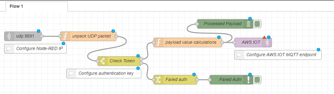
Now we need to configure the AWS IoT MQTT node. Click on the node to open its settings. The top-level settings have already been configured in the flow you imported. Click on the edit icon next to the Server field.
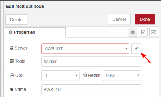
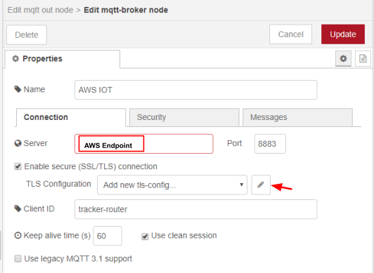
Paste your AWS IoT endpoint URL into the Server field, then click the edit icon next to the TLS Configuration field.
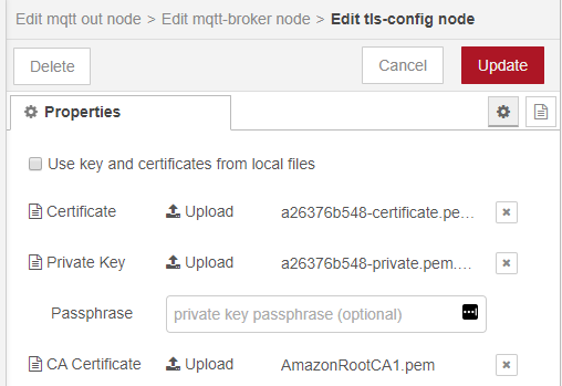
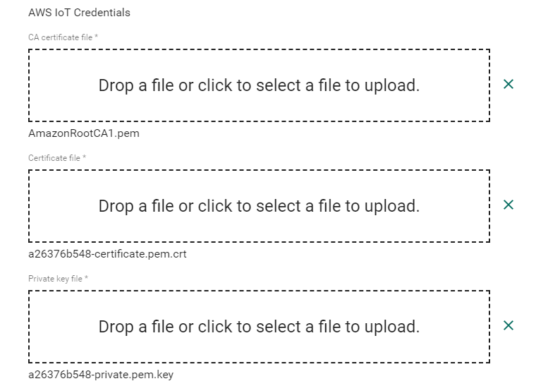
Here you need to upload the certificate, private key and CA certificate generated by AWS IoT Core.
When you have finished configuring the node, you can deploy the flow, and the MQTT node should show that it is connected.
Next we need to generate a unique 256-bit key to add some rudimentary device authentication. Go to randomkeygen.com and copy one of the randomly generated CodeIgniter Encryption Keys. Open the settings for the Check Token node, and paste the 256-bit key into the field shown below.
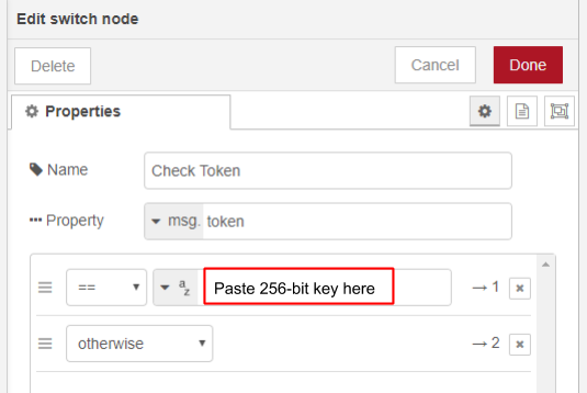
You’ll also need this key to configure the tracking device.
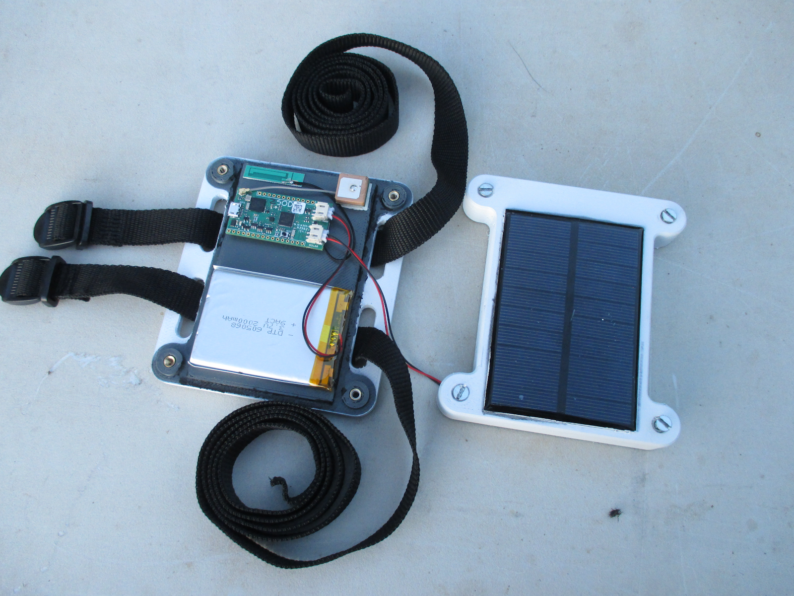
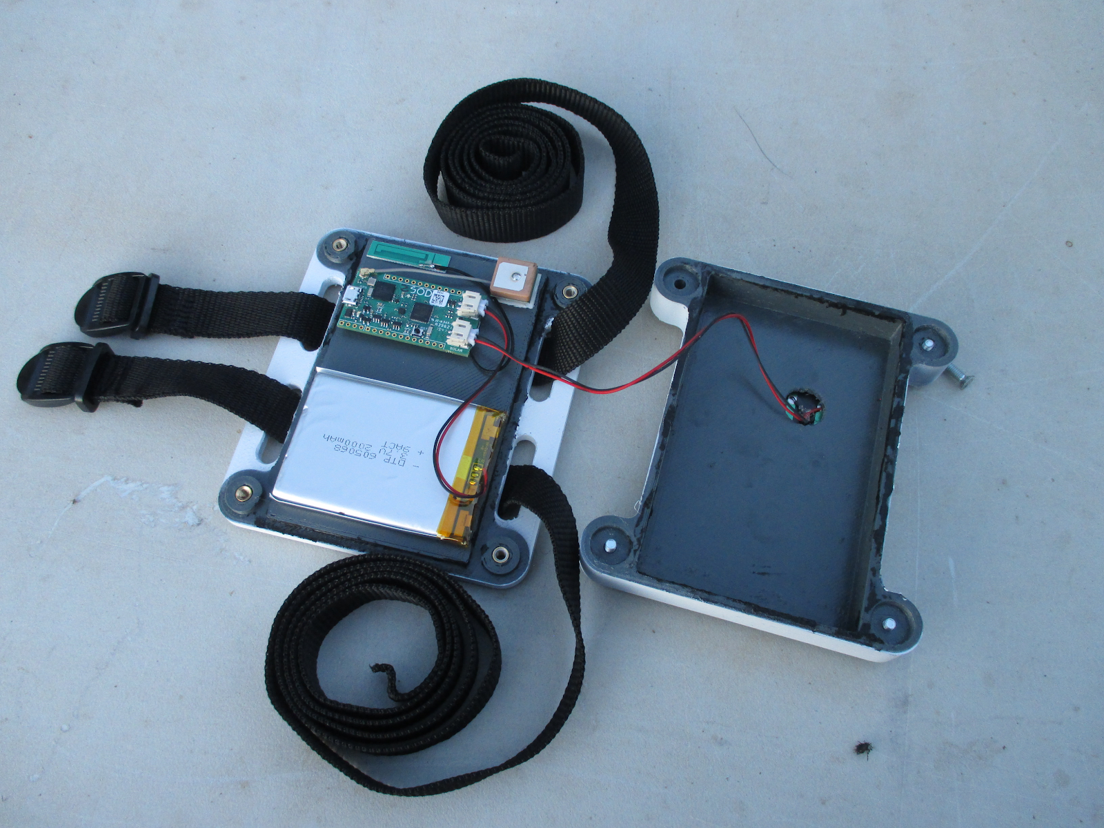
Tracking Device Hardware Components
You’ll need the following components to build the tracking device
- Sodaq SFF (GSM and GPS antennas included)
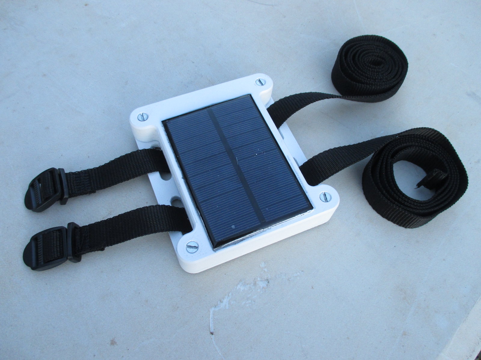
- 3D printed enclosure, preferably in white ASA filament
- 2000mAh Li-Po battery with JST connector. The available battery space is 72x72x12mm.
- 5V Solar Panel, 102x76mm or smaller, with a JST connector. I used a 5V 170mA (0.9W) panel
- 4x M4 threaded inserts. Any M4 insert sized for a 5.7mm hole should work
- 4x M4x20 Countersunk Screws
- Double sided tape
- 2x 1” straps with buckles or ladder locks. Make sure it’s long enough to fit the livestock in question.
Print the 2 enclosure parts, with 0.2 mm layer height and 25 mm infill. I used a 0.6mm nozzle on an Ultimaker 2. ASA filament is preferred for its impact and UV, and temperature resistance. The inside of my enclosure hit 70 °C while sitting outside on an average sunny South African day, which is hot enough to make PLA get soft. My enclosure was printed in grey, but I spray painted the outside surface white to reduce the amount of solar energy it absorbs and help it stay cooler during the heat of the day.
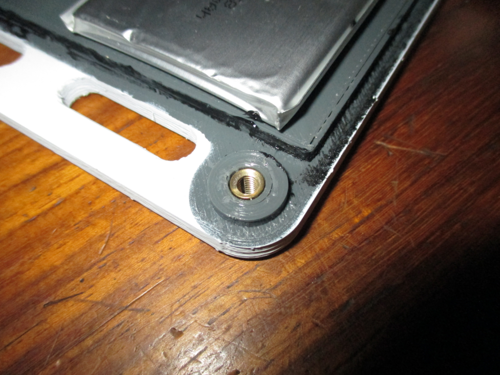
Once your enclosure is printed, push the M4 threaded insert into the 4 holes in the base of the enclosure, using a soldering iron. Using the Fusion 360 files on Thingiverse, you can also add hexagonal recesses the bottom of the base to fit normal nuts instead of threaded inserts.
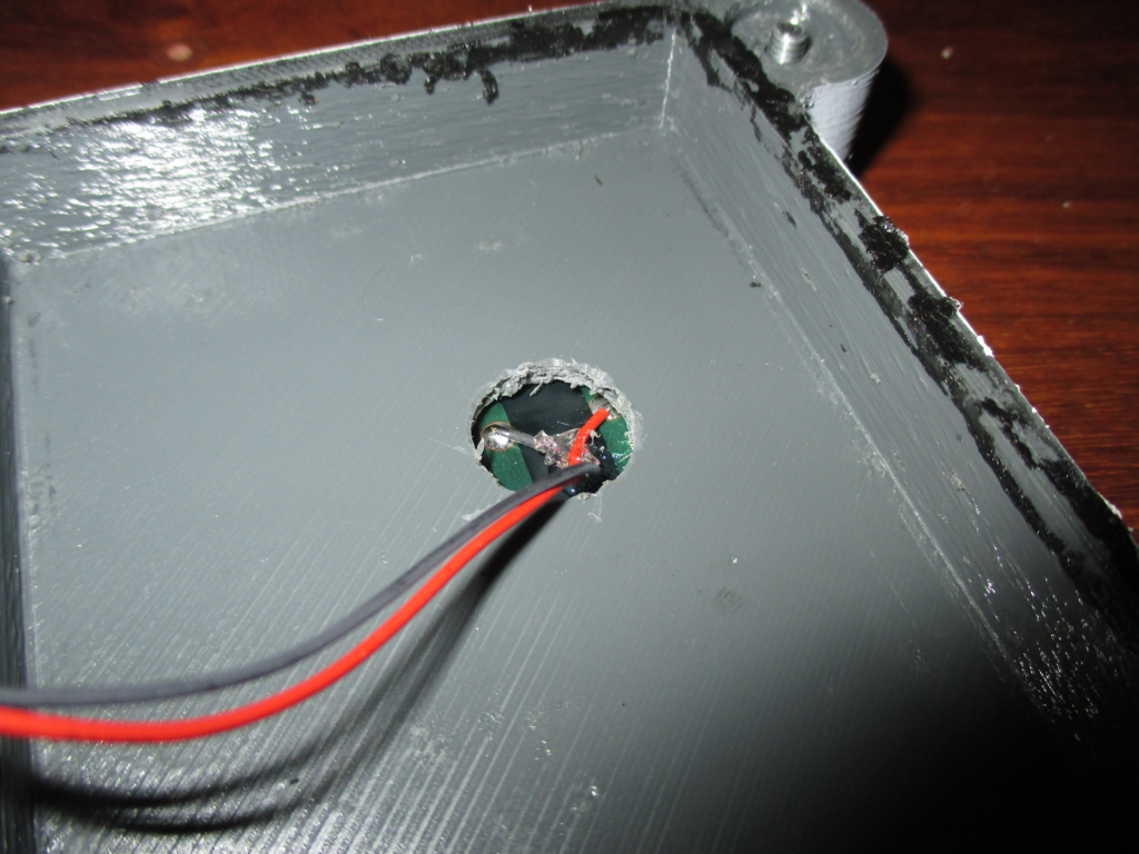
Carefully fit your solar panel onto the cover of the enclosure. It must sit off-centre on the cover to ensure that the GPS antenna is not blocked. Mark and drill a appropriately sized hole in the cover to feed the solar panels wires through. If possible make the hole big enough to go around the solder points on the solar panel, allowing it to sit completely flush on the cover. Glue the solar onto the cover, making sure it is sealed all around to prevent water from seeping into the enclosure. I used Loctite SI 5940, a silicone sealant/adhesive.
Using double-sided tape, attach the Sodaq SFF, antennas and battery to the enclosure base. The GPS must be mounted on the outer edge of the base, to ensure it isn’t blocked by the solar panel. Connect the battery and solar panel to the appropriate connectors on the Sodaq SFF. Once all the firmware is loaded and working (next step), you can screw on the enclosure cover, being careful to not pinch any wiring. To properly waterproof the enclosure, add some silicone on the edge of the cover before closing.
Device Firmware
We will be programming the Sodaq SFF using the Arduino IDE, so make sure you have the latest version installed. Once you’re ready, you need to add the Sodaq SAMD board files URL. Open the Arduino IDE and click File > Preferences and add the following to “Additional Boards Manager URLs:
http://downloads.sodaq.net/package_sodaq_samd_index.json
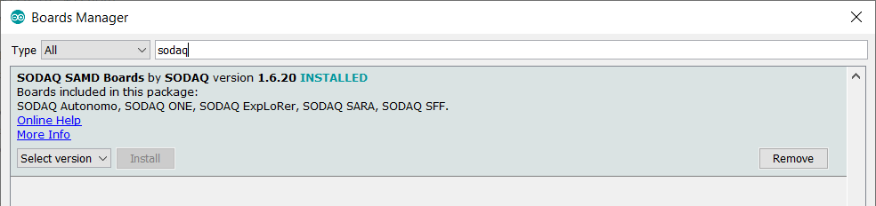
To install the board files, go to Tools > Select Board > Board Manager. Search for “Sodaq”, and install “Sodaq SAMD Board”
Now that your IDE is properly set up, clone or download the forked Universal Tracker firmware from GitHub where you’ll also find the latest instructions for compiling and configuring the firmware. The primary things you need to configure is:
- IP address for your Node-RED instance
- 256-bit key that you set in the Check Token node
- Device ID. I used “tracker1”
All the instruction are in the repository README.
How to Set Up Hologram SIM
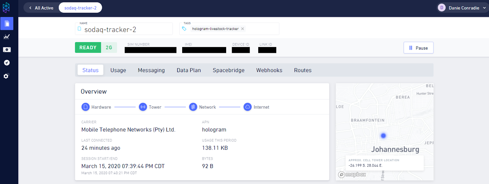
If you’re using a Hologram SIM, you can activate it by logging into your Hologram account, and following this guide. If you’re using a different SIM, you’ll also need to configure the APN of the service provider on the tracking device.
You can use the single device page to confirm connectivity and to view information such as cell tower location, mobile network, and radio access technology (i.e. 4G, 3G, 2G).
How to Set Up ThingsBoard and Integrate with AWS IoT
To get started with ThingsBoard sign up for a ThingsBoard PE Cloud Edition Trial Account. This will setup up a account with a bunch of demo data, which we will ignore.
After our account is ready, the next step is to set up the data converter. It parses incoming JSON packet from AWS IoT, and assigns device attributes and telemetry values in ThingsBoard. In the sidebar menu select Data Converters. A few demo converters will be visible, but we’ll be uploading our own.
In the bottom right corner, click Add new data converter > Import Converter. Upload the tracker_json_uplink.json file that is in the tracker-router-node-red repository.
To set up the integration to AWS IoT, select Integrations in the sidebar menu. In the bottom right corner click Add new integration. Use the same endpoint and certificates as for the MQTT node in Node-RED, but use a different client ID, otherwise it will not allow ThingsBoard to connect via MQTT. The Uplink data converter must be the converter that you just uploaded.
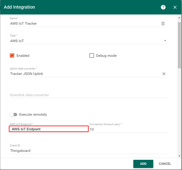
Add the same MQTT topic as was used in Node-RED, otherwise the server will reject the connection.
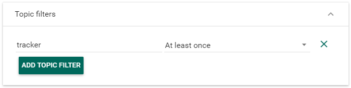
Click Add to finalize the integration.
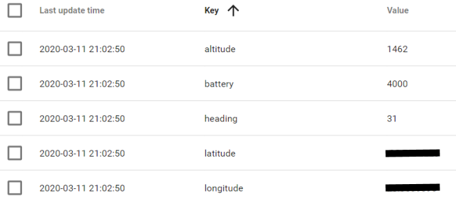
Before creating the dashboard, we need to test that data is being received from the Sodaq tracking device. Make sure that it’s transmitting successfully. Open your Node-RED dashboard and keep an eye on the debug pane to for incoming data.
Now we can create the dashboard. In the sidebar menu, go the Dashboard Groups > All. In the upper right, click Import dashboard. Now click Open Dashboard on the Dashboard you just created.

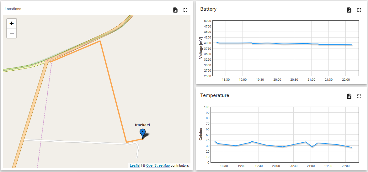
If you used the same Device ID as myself (“tracker1”), your dashboard should be working right from the start, and should look something like this
If you used a different device ID, you need to specify it by clicking Enter edit mode in the bottom right, and then Entity aliases in the top right.
Click Edit Alias and select your Device ID in the Device field. Now your dashboard should be fully working.
Conclusion
Now we have a proof-of-concept prototype system to use for testing. Before you start adding polish and new features to the project, go to a prospective client and test it as if for a few days to get some feedback. Don’t worry that it’s still a bit rough around the edges, the goal is to figure out which improvements need to be prioritised, and not waste time on features that are not critical for the client.
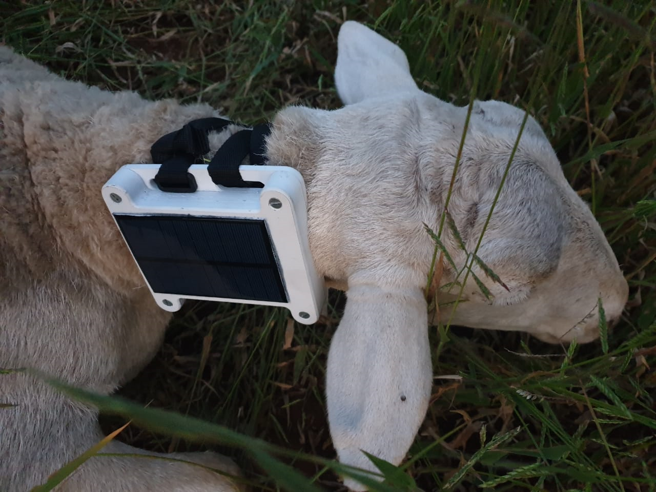
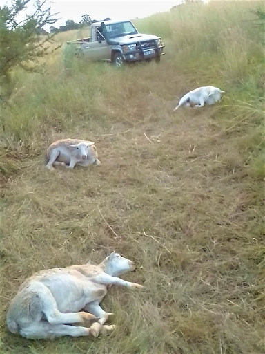
Attaching the tracker to a sheep, right after it was recovered following a theft attempt
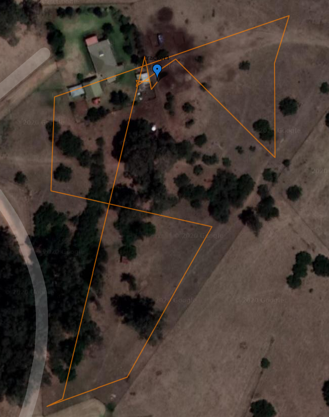
A day in the life of a sheep. Waypoints were recorded at 30min intervals
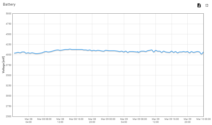
Battery voltage over a period of two days. The small solar cell is barely keeping up with the power usage. This is why optimising power consumption is so important in small solar and battery powered devices
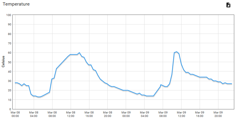
temperature inside the enclosure. Those +60 °C spikes are from direct sunlight on days with ambient temperatures below 30 °C. You will need to consider what effect this could have on the long term performance of outdoor devices
Possible improvements can include:
- Fine-tune the “on-the-move” accelerometer thresholds in the device firmware
- Set up geofencing, alarms and smart phone notifications in ThingsBoard.
- Reducing tracker size and power consumption
I hope this guide has helped you in creating your own tracking device, and please let me know on twitter if you have!
Danie Conradie (@MongooseCurious)is a South African engineer and maker, and a contributor at Hackaday. For tech that solves real problems, you can contact him at Twitter, Instagram or Hackaday.